Lab 6: Orientation PID
03.11.2025 - 03.18.2025
Prelab
In this lab, a PID controller is implemented to achieve closed-loop control of the robot's orientation. The IMU was used to measure orientation, and the software would power the motor drivers to turn either left or right to maintain that orientation.
PID Overview
A PID controller consists of three key parts:
These parts together form the PID control equation, which I took from Lecture 7:
This equation calculates the PID input value 𝑢(𝑡) using the error 𝑒(𝑡), which represents the difference between the desired and current values. In this lab, the error corresponds to the difference between the target distance from the wall (1 ft) and the robot’s actual distance. The resulting PID input value directly influences the robot’s speed. Proportional control scales the error by a constant K_p, providing an immediate response. Integral control accumulates past errors by integrating over time and multiplying by K_i, helping to eliminate steady-state error. Derivative control predicts future error changes by computing the rate of change of the error and multiplying by K_d, improving system stability.
Bluetooth
Much of my setup for this lab is similar to Lab 5's setup, as the general idea is the same.
Before starting the lab tasks, I modified my code to make data collection and debugging easier. As such, I added a boolean flag, pid_ori_on, that would keep track of whether or not to use the pid controller. I also added three more command types: START_PID_ORI, STOP_PID_ORI, and GET_PID_DATA_ORI. These would be easily callable using Bluetooth, and helped make running the car and collecting data much more convenient.
The START_PID_ORI case set pid_ori_on to true and initialize the variables needed to implement PID, including the pid index and any error variables. The STOP_PID case sets the pid_ori_on flag to false and stops the car.
case START_PID_ORI:
{
    pid_ori_i = 0;
    error_ori = 0;
    prev_error_ori = 0;
    error_sum_ori = 0;
    pid_ori_on = true;
    break;
}
The third case that I added was GET_PID_DATA_ORI, which returns time, angle, pwm, and error. I implemented this in the same way as in previous labs.
for (int i = 0; i < num_data_msgs; i++)
{
    tx_estring_value.clear();
    tx_estring_value.append(pid_times[i]);
    tx_estring_value.append(",");

    tx_estring_value.append(pid_current_angles[i]);
    tx_estring_value.append(",");

    tx_estring_value.append(pwm_data[i]);
    tx_estring_value.append(",");

    tx_estring_value.append(pid_err[i]);

    tx_characteristic_string.writeValue(tx_estring_value.c_str());
}
The last part of the bluetooth code was on the Python end, where I would receive the data to plot and analyze. I used a notification handler similar to the ones from previous labs.
data = ""
timeArr = []
angle_pid = []
pwm_pid = []
error_pid = []

def notification_handler_pid(uuid, array):
    s = ble.bytearray_to_string(array)
    data = s
    # print(data)
    if "," in data:
        arr = s.split(",")
        timeArr.append(int(arr[0]))
        angle_pid.append(float(arr[1]))
        pwm_pid.append(float(arr[2]))
        error_pid.append(float(arr[3]))
DMP
In the lab handout, it is suggested to enable the digital motion processor (DMP) to allow the IMU to perform real-time calibration and drift correction. This would provide more reliable data. It was previously disabled because it requires 14 kB of additional program memory on the host microprocessor. However, I decided it would be beneficial to re-enable it for this lab, as it is heavily reliant on good IMU data.
To enable the DMP again, I followed the instructions in the lab handout link, and uncommented the line defining ICM_20948_USE_DMP in SparkFun_9DoF_IMU_Breakout_-_ICM_20948_-_Arduino_Library
I also followed the instructions to put in their given code into our setup function:
    bool DMP_success = true;
    // Initialize the DMP
    DMP_success &= (myICM.initializeDMP() == ICM_20948_Stat_Ok);
    // Enable the DMP Game Rotation Vector sensor
    DMP_success &= (myICM.enableDMPSensor(INV_ICM20948_SENSOR_GAME_ROTATION_VECTOR) == ICM_20948_Stat_Ok);
    // Set the DMP output data rate (ODR): value = (DMP running rate / ODR ) - 1
    // E.g. for a 5Hz ODR rate when DMP is running at 55Hz, value = (55/5) - 1 = 10.
    DMP_success &= (myICM.setDMPODRrate(DMP_ODR_Reg_Quat6, 4) == ICM_20948_Stat_Ok);
    // Enable the FIFO queue
    DMP_success &= (myICM.enableFIFO() == ICM_20948_Stat_Ok);
    // Enable the DMP
    DMP_success &= (myICM.enableDMP() == ICM_20948_Stat_Ok);
    // Reset DMP
    DMP_success &= (myICM.resetDMP() == ICM_20948_Stat_Ok);
    // Reset FIFO
    DMP_success &= (myICM.resetFIFO() == ICM_20948_Stat_Ok);
    // Check success
    if (!DMP_success)
    {
        Serial.println("Enabling DMP failed!");
        while (1)
        {
            // Freeze
        }
    }
The handout also provided example code for a loop function, which I used in my PID implementation.
PI Control
I began my PID implementation by using both proportional and integral control (PI) using the knowledge we learned from class.
current_time = millis();
float pid_dt = current_time - prev_time;
prev_time = current_time;

icm_20948_DMP_data_t data;
myICM.readDMPdataFromFIFO(&data);

if ((myICM.status == ICM_20948_Stat_Ok) || (myICM.status == ICM_20948_Stat_FIFOMoreDataAvail))
{
    if ((data.header & DMP_header_bitmap_Quat6) > 0)
    {
        double q1 = ((double)data.Quat6.Data.Q1) / 1073741824.0; // Convert to double. Divide by 2^30
        double q2 = ((double)data.Quat6.Data.Q2) / 1073741824.0; // Convert to double. Divide by 2^30
        double q3 = ((double)data.Quat6.Data.Q3) / 1073741824.0; // Convert to double. Divide by 2^30

        current_angle = quaternion_to_yaw(q1, q2, q3);
    }
}

error_ori = current_angle - target_angle;
double err_d = (error_ori - prev_error_ori) / pid_dt;
double err_i = err_i + (error_ori * pid_dt);

// Calculate speed control signal
The if statement includes functionality from the DMP's example code, as mentioned above. This function is then called in the main loop, where the data arrays are populated with sensor readings and analyzed. Specifically, the code reads quaternion data from the ICM-20948 IMU sensor. It extracts orientation data, converts it into a usable format, and calculates the yaw angle. This yaw angle is then compared to a target angle to compute an orientation error, which is used in a PID control loop. The error values—including proportional, derivative, and integral terms—are updated to generate a control signal for speed adjustment, ensuring precise motion control.
if (pid_ori_on)
{
    int pwm;
    pwm = pid_ori(Kp, Ki, Kd, target_angle);

    if(curr_time - start_time > 20000)
    {
        pid_on = false;
        drive(0, 0);
    }

    if (pid_i < num_data_msgs)
    {
        pid_current_angles[pid_ori_i] = current_angle;
        pwm_data[pid_ori_i] = pwm;
        pid_times[pid_ori_i] = (float)millis();
        pid_err[pid_ori_i] = error_ori;
        pid_ori_i++;
    }
}
In the main loop, we first check that pid is turned on for orienation. Then, we use the pid_ori function mentioned above to find the new pwm value based on the gains and target angle. A timeout condition is implemented to disable the PID control after 20 seconds by setting pid_on to false and stopping motion using drive(0, 0).
Kp = 0.05
I first tried using the same PID values as in Lab 5, which was Kp=0.05, Ki=0, and Kd=0. When I ran this, however, the car would not move, and I saw that many PWM values of 0 were being printed out when I had print statements to debug.
Kp = 4.0, Ki = 0.0001
The next thing I tried was increasing my Kp by a lot, setting it all the way up to 4.0. I tested Kp values of 2 and 3.5 as well, but found that Kp=4.0 yielded the best results. Furthermore, the car would struggle when Ki was set to 0, so I decided to tweak the Ki value and see if that would help. After this fix, the car was able to correct itself when shaken off its preferred orientation.
Using my pre-set Bluetooth functions, I took and plotted data of the robot correcting itself when moved from its heading.
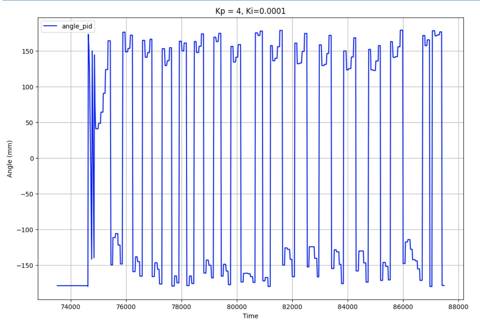
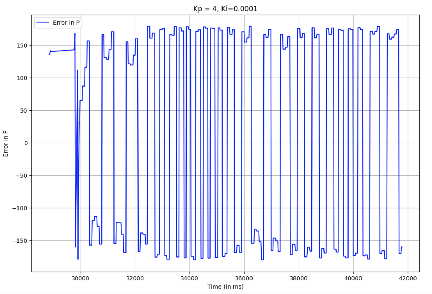
The plot for angles is slightly strange, as I set the desired target to be 0. I think this is due to the wrapping around of degree values, and thats why the car is osillating so much. As you can see from the video, the car doesn't oscillate fully from -180 to 180 degrees, it just moves slightly around the zero degree mark. The error graph visually matches the angle values in pattern.
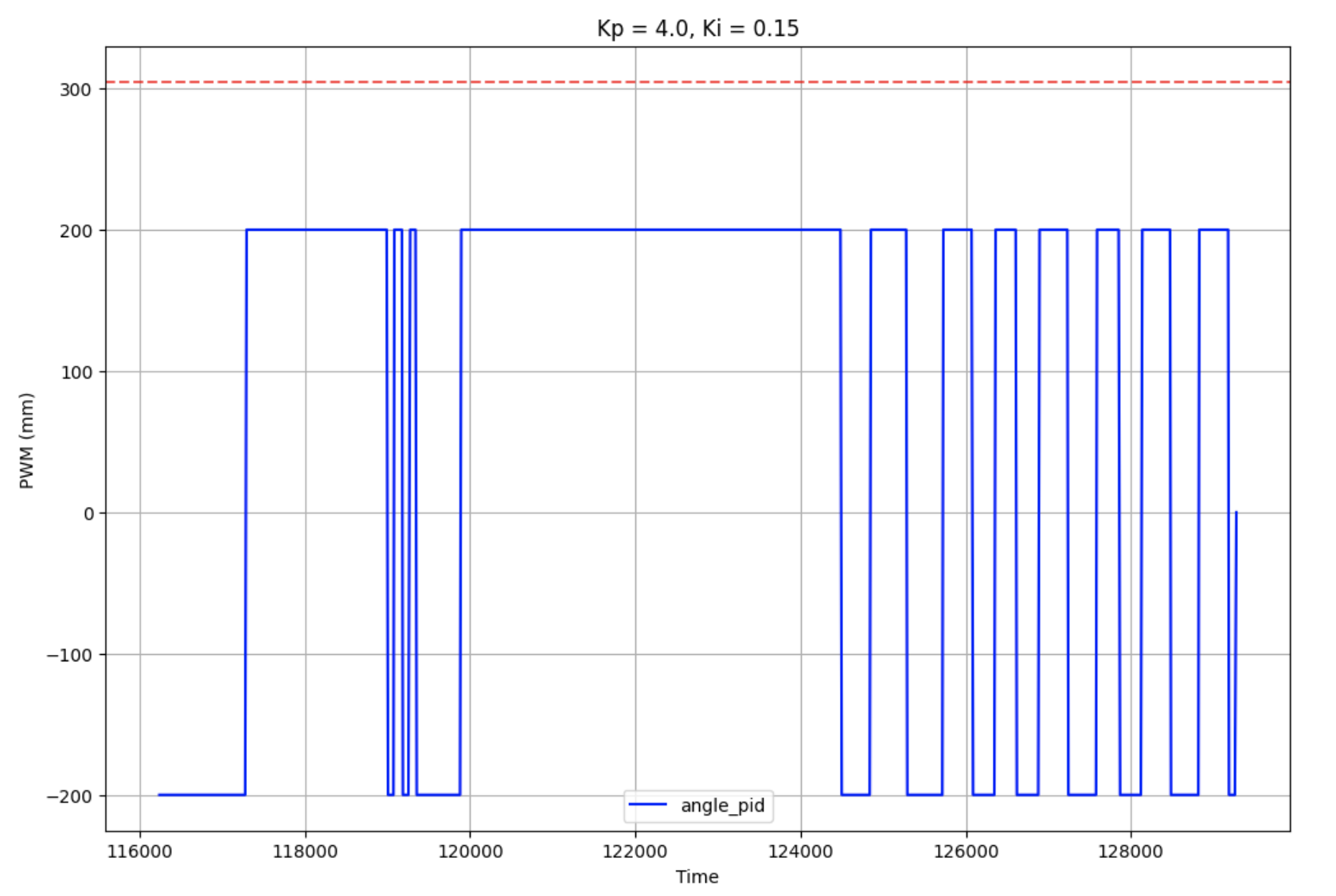
I also plotted the PWM data for a similar run with the same Kp and Ki values, also with correcting. The PWM values are always either -200 or 200, likely due to some form of integer multiplication issue in my code (ie a value was assigned to an integer when it should have been a float or double). I set my maximum pwm speed to 200, so this was a good check to make sure that these constraints were being held.
Notes
While testing and messing around, I observed that every time I ran START_PID_ORI, the car would first spin around rapidly and then calm down to smaller oscillations that were still bigger than what was shown in the video above. It would take some take with these bigger oscillations, correcting itself when necessary, and then it would go back to very small oscillations again. I believe this is due to some kind of calibration or warming up. A video of this happening is attached:
Speed and Sampling Rate
I used the same method as Lab 5 to check the sampling rate of the IMU readings and the PID loop. I etermined that the PID loop without taking sensor measurements took ~9 ms, which is a frequency of 111.11 Hz. The ToF sampling period was 40 ms, or ~25 Hz.
Conclusion
My issues with my battery from the last two labs culminated into a rough time with this lab, as I wouldn't even be able to power through one test before the battery died on me. I was able to use the battery of someone I was working with, and kept using it.
References
I referred to Nila Narayan's Lab 6 report from last year. Furthermore, I worked with Jennie Redrovan and Sana Chawla on this lab. As previously mentioned, my battery wasn't working, and we were left with just one working battery. Thus, we all used the same hardware but ran our code separately.